Co-author, with Josh Elquiero & Humza Rubel
This research project set out to find the optimal vortex generator size and position for delaying stall on a small NACA 4410 wing, pairing physical wind tunnel testing with CFD simulation. A 3D-printed modular airfoil with five interchangeable slot positions let the team isolate the effect of generator size and placement across 90 total test configurations.
Vortex generators can delay flow separation and push back the stall angle of attack, but design guidance for sizing and placing them is limited. The team hypothesized that larger generators placed further forward (nearer the leading edge) would produce the greatest increase in stall angle. To test this, a singular 3D-printed NACA 4410 airfoil was built with five spanwise slots that could hold either flat control plates or interchangeable small, medium, or large vortex generator plates.
Wind tunnel testing ran at 1200 rpm (about 50 mph freestream), sweeping angle of attack from 0° to 25° in 5° increments for every generator size and position combination — 90 configurations in total, each captured with axial and normal force measurements from a sting-mounted balance.
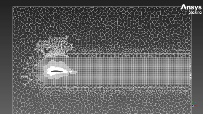
In parallel, ANSYS 2025 R2 simulations using a k-omega SST turbulence model and a Poly-Hexcore mesh (1.9–3.4 million cells depending on configuration) modeled the first-position case for each generator size across a smaller sweep of angles of attack, keeping y+ values below 3 for adequate boundary-layer resolution. The CFD wasn't meant to "validate" the experiment so much as to explain the flow physics behind the measured lift and drag curves.
The data told a more nuanced story than expected. Medium-sized generators at the leading edge delayed stall to 20°, well past the ~14° baseline — but the large generators at the same forward position actually underperformed, producing less lift at the critical angle than the medium size. Past a certain size, the generator behaves more like an obstruction that trips turbulence too early, bleeding energy from the flow before it reaches separation.
Looking at overall efficiency (lift-to-drag ratio) rather than stall angle alone told a different story still: a Kriging surrogate model fit to the experimental dataset predicted the true optimum was a medium-sized generator placed near the trailing edge, reaching a modeled L/D of 56.99. Forward placement delays stall at high angles of attack, but its drag penalty at cruise angles makes it inefficient overall — rearward placement holds onto most of the post-stall benefit while cutting that penalty.
The CFD also surfaced a transient effect that force measurements alone couldn't capture: at 20° angle of attack, the simulations showed a periodic vortex-shedding oscillation at the leading edge, most pronounced for the small generator and nearly fully damped for the large one — suggesting that even where oversized generators hurt efficiency, they produce a more stable post-stall flow structure.
The original hypothesis — bigger and further forward is always better — didn't hold up. There's a critical size and position past which additional vortex generator size stops helping and starts hurting performance, and evaluating design choices by lift-to-drag ratio rather than stall angle alone changes the optimal answer entirely.